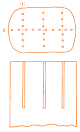
Hole Design for Concrete
General Concepts For Breaking Of Concrete
| d | 32 - 35 mm |
| 1½ " - 1¾ " | |
| L | 40 - 60 cm |
| 1´ 4" - 2´ | |
| D | 70% of Height |
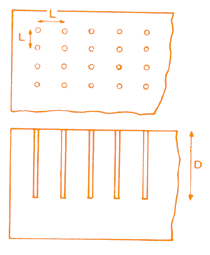
Reinforced Concrete
| d | 35 mm | 38 - 44 mm |
| 1 3/8" | 1 ½" - 1 ¾" | |
| L | 20 - 25 cm | 30 - 40 cm |
| 8" - 10" | 1'-1'4" | |
| D | 90% of Height | |
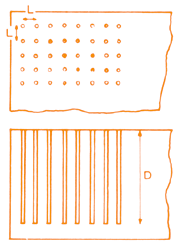
Thin Concrete
| d | 32 - 38 mm |
| 1 ¼" - 1 ½" | |
| L | 25 - 30 cm |
| 10" - 1' | |
| D | Almost Wall Thickness |
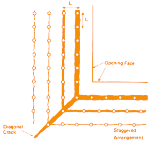
| d | 32 - 38 mm | 25 mm | 32 - 38 mm |
| 1 ¼"-1 ½" | 1" | 1 ¼" - 1 ½" | |
| L | 25 - 30 cm | 10 cm | 10 - 15 cm |
| 10" - 1' | 4" | 4"-6" |
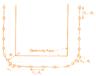
| d | 38 - 44 mm |
| 1 ¼" - 1 ½" | |
| L | 25 - 30 cm |
| 10" - 1' |
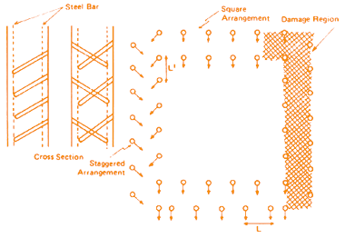
| d | 38 - 44 mm |
| 1 ½" - 1 ¾" | |
| L | 25 - 30 cm |
| 10" - 1' |
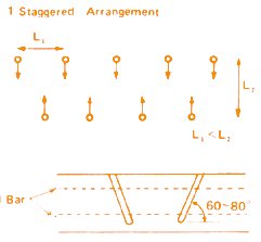
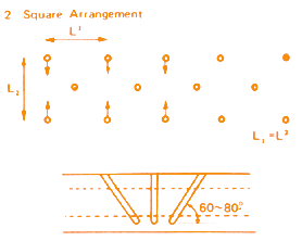
| d | 38 - 44 mm |
| 1 ½" - 1 ¾" | |
| L | 25 - 30 cm |
| 10" - 1' |
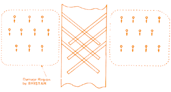
Mass Concrete
| Concrete | Reinforced Concrete | |
| d | 38 - 51 mm | 38 - 44 mm |
| 1 ½" - 2" | 1 ½" - 1 ¾" | |
| L | 50 - 90 cm | 40 - 60 cm |
| 1'8" - 3' | 1'4" - 2' |
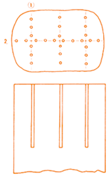
Pile Foundation
| d | 38 - 44 mm |
| 1 ½"-1 ¾" | |
| L1 | 20 cm |
| 8" | |
| L2 | 20 - 25 cm |
| 8" - 10" |
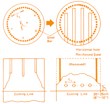
Thick Wall
| d | 38 - 44 mm |
| 1 ½" - 1 ¾" | |
| L | 30 - 60 cm |
| 1' - 2' |
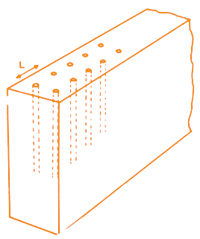
When perpendicular cracks to wall face are necessary:
Pier / Bridge / Foundation
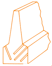
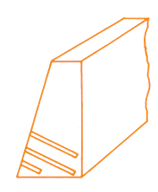
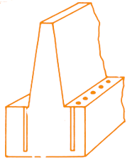
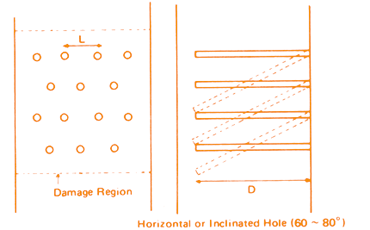
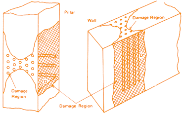
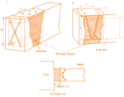
Drilling pattern depends on the shape of the structure and the site situation.
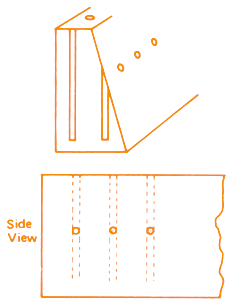
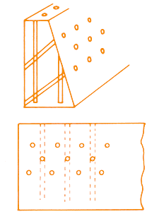
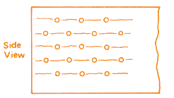
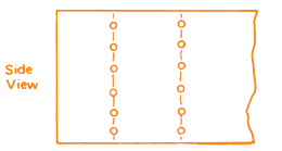
Zone Demolition
| d | 38 - 44 mm |
| 1 ½" - 1 ¾" | |
| L | 30 - 40 cm |
| 1' - 1'4" | |
| D | 90% of Width or Height |
| d | 38 - 44 mm |
| 1 ½" - 1 ¾" | |
| L | 30 - 40 cm |
| 1' - 1'4" | |
| D | 90% of Width or Height |
| d | 38 - 44 mm |
| 1 ½" - 1 ¾" | |
| L | 30 - 40 cm |
| 1' - 1'4" | |
| D | 90% of Width or Height |
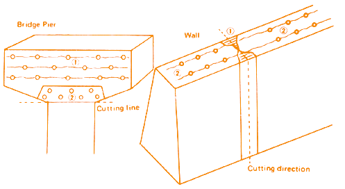
Delayed Filling
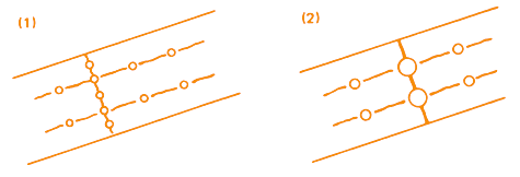
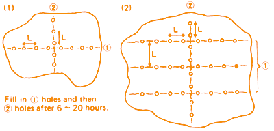
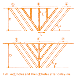
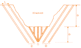
Fill in (1) holes then (2) holes after a suitable delay.
This can be applied for controlling the cracking direction (See below).
| d | 32 - 35 mm | 44 - 51 mm |
| 1 ¼" - 1 3/8" | 1 ¾" - 2" | |
| L | 30 - 40 cm | 60 - 90 cm |
| 1' - 1'4" | 2' - 3' | |
| D | 70% of Height | |
| d | 38 - 51 mm |
| 1 ½" - 2" | |
| L | 30 - 60 cm |
| 1' - 2' | |
| D | 1 - 1.8 m |
| 3' - 6' | |
| ⊖ | 45°-60° |
| Concrete | Reinforced Concrete | |
| d | 38 - 51 mm | 38 - 44 mm |
| 1 ½" - 2" | 1 ½" - 1 ¾" | |
| L | 50 - 90 cm | 40 - 60 cm |
| 1'8" - 3' | 1'4" - 2' |
